Saturn-60 Assembly Guide
Thanks for buying a Saturn-60! Here's our guide of how to put it together:
Please note: the entire assembly process may require several hours. Be patient, take breaks, and try not to get too frustrated (ノಠ益ಠ)/
♠️ You can do this! \(°□°)/ ♠️
STEP 1: Verify all parts are included:
Part No.
Description
Quantity
Note
4
PCB
1
(if ordered)
6
M3 x 0.5 x 8 mm Screws
20
10
Saturn-60 Badge
1
Adhesive backing
11
Ace Serial Number Plate
1
12
M3 Nuts
4
For Ace Serial Plate
13
M3 Washers
8
Only recommended for screws on the bottom of the case
15
Rubber Feet
4
non-marking Polyurethane
16
2.5mm Hex Key
1
Golden
STEP 2: Test the PCB
This step is optional but recommended. It tests the Panel-Mount cable as well. Skip to Step 3
Attach the Panel Mount Type-C [Part No. 5] cable to the Connector on the PCB, then connect to the device to your computer.
Open a typing tester [QMK Key Tester] using your browser and use tweezers or a paperclip📎to short the pads on the pcb.
if no keycode shows up for a particular switch, it may be a "function key" to change to a different function layer

Click here to see the full default keymap (Step 12)
STEP 3: Install Stabilizers
First, assemble and install your Keycap Stabilizers (sold separately) on the PCB. The Titan60 requires screw-in stabilizers.
STEP 4: Side-Glow RGB Wires (Optional)
If you are not doing this, Skip to Step 5
NOTE: it will be very difficult to add the side-glow after Step 5! If you are not sure whether or not you will want the sideglow later, just solder the wires to the PCB now, or buy these 3-pin, 2.54-pitch Screw Terminals and solder those on.
Strip the wires on both ends, and peel back the clear rubber a bit on the RGB strips as shown:
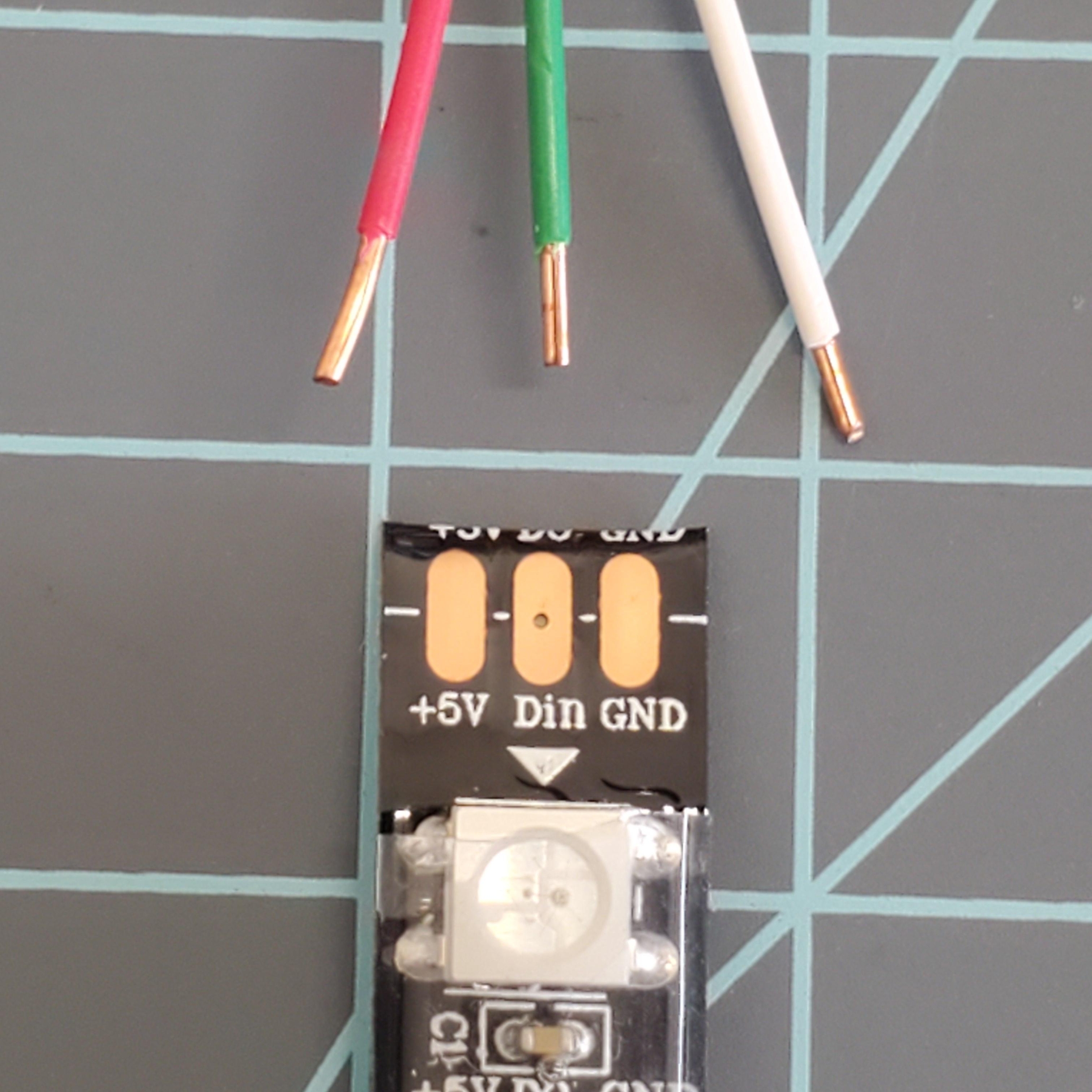
NOTE: The strip has a direction as noted by the arrow. The arrow should point AWAY from the PCB, when installed.
Add some solder to the pads on the strip:
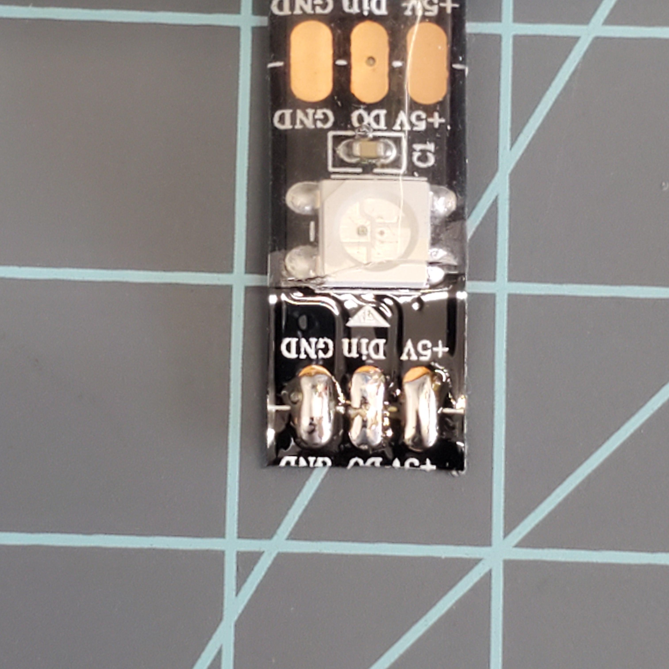
Now solder the wires onto the pads. It helps to use something heavy to hold the RGB Strip down while you do this:
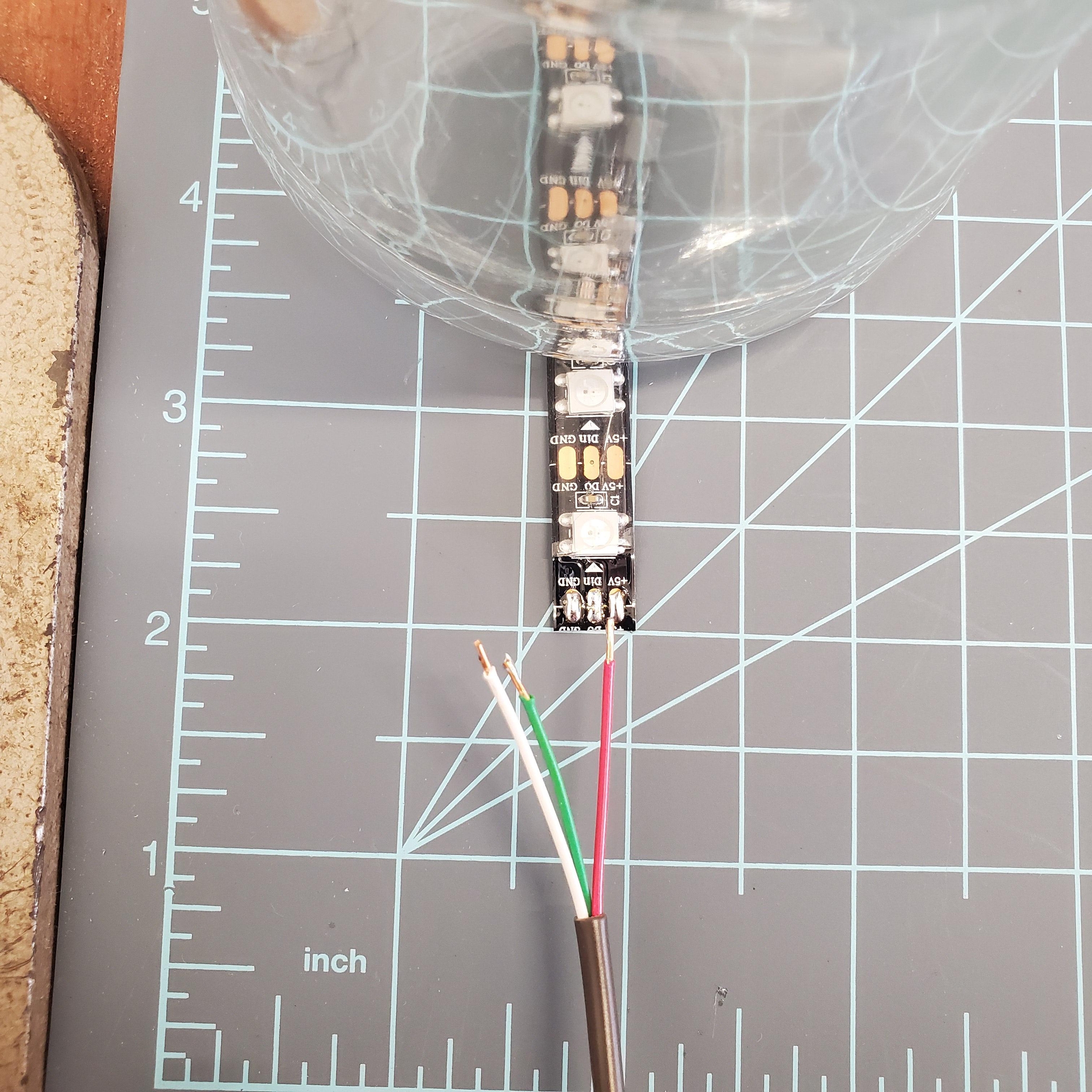
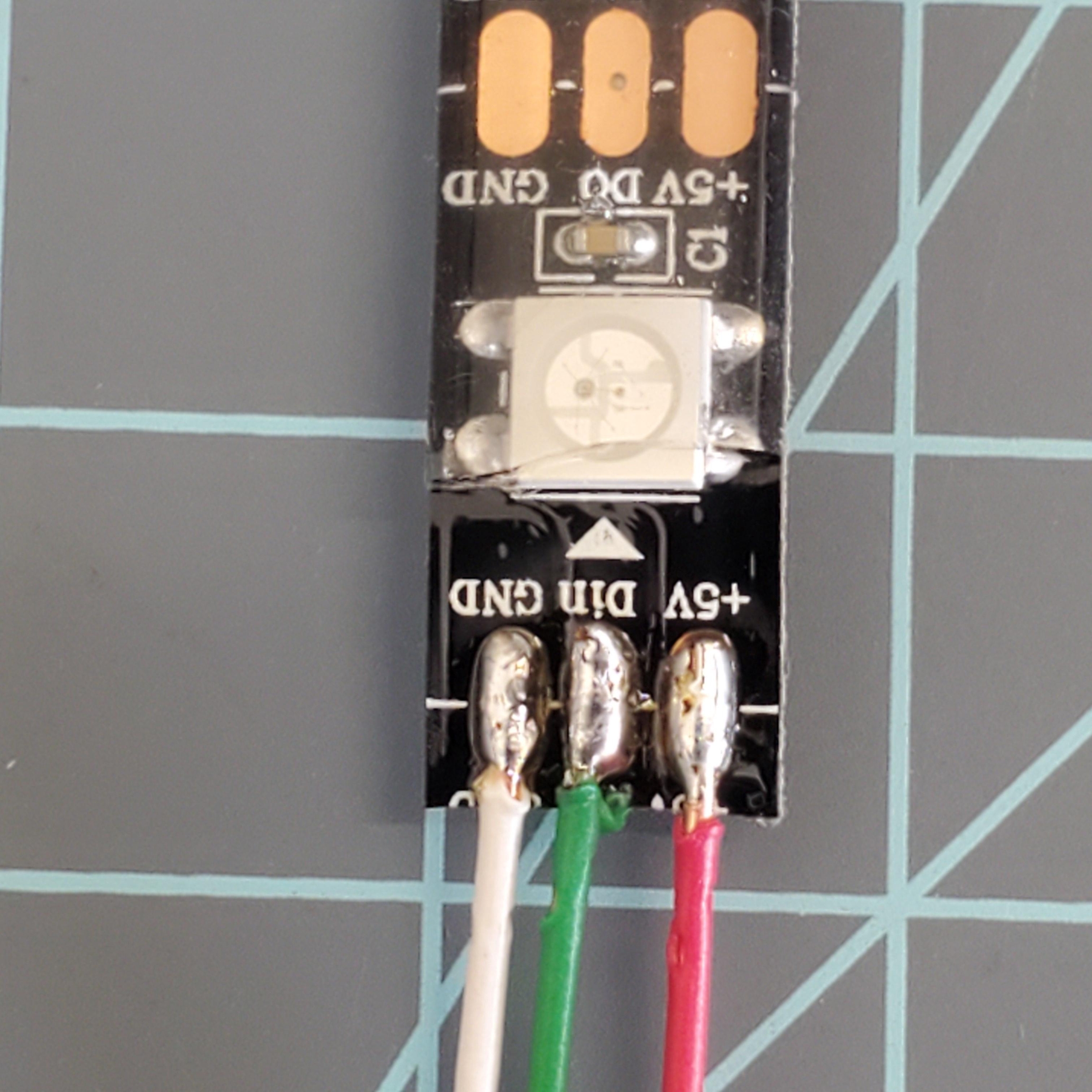
Optional: cover the soldered connection with heatshrink tubing or tape.
Solder the other end of the wires to the PCB. NOTE: The wires must be put in the correct hole, as labeled on the PCB, and on the RGB strips:
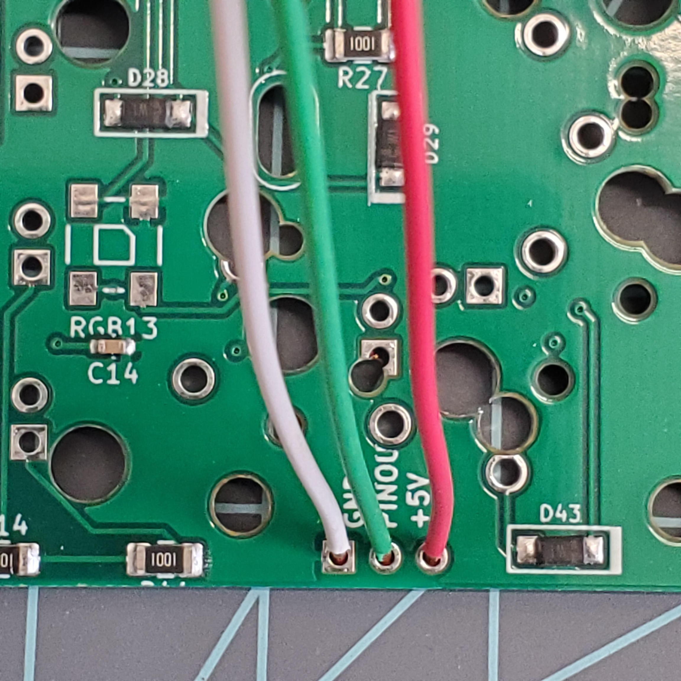
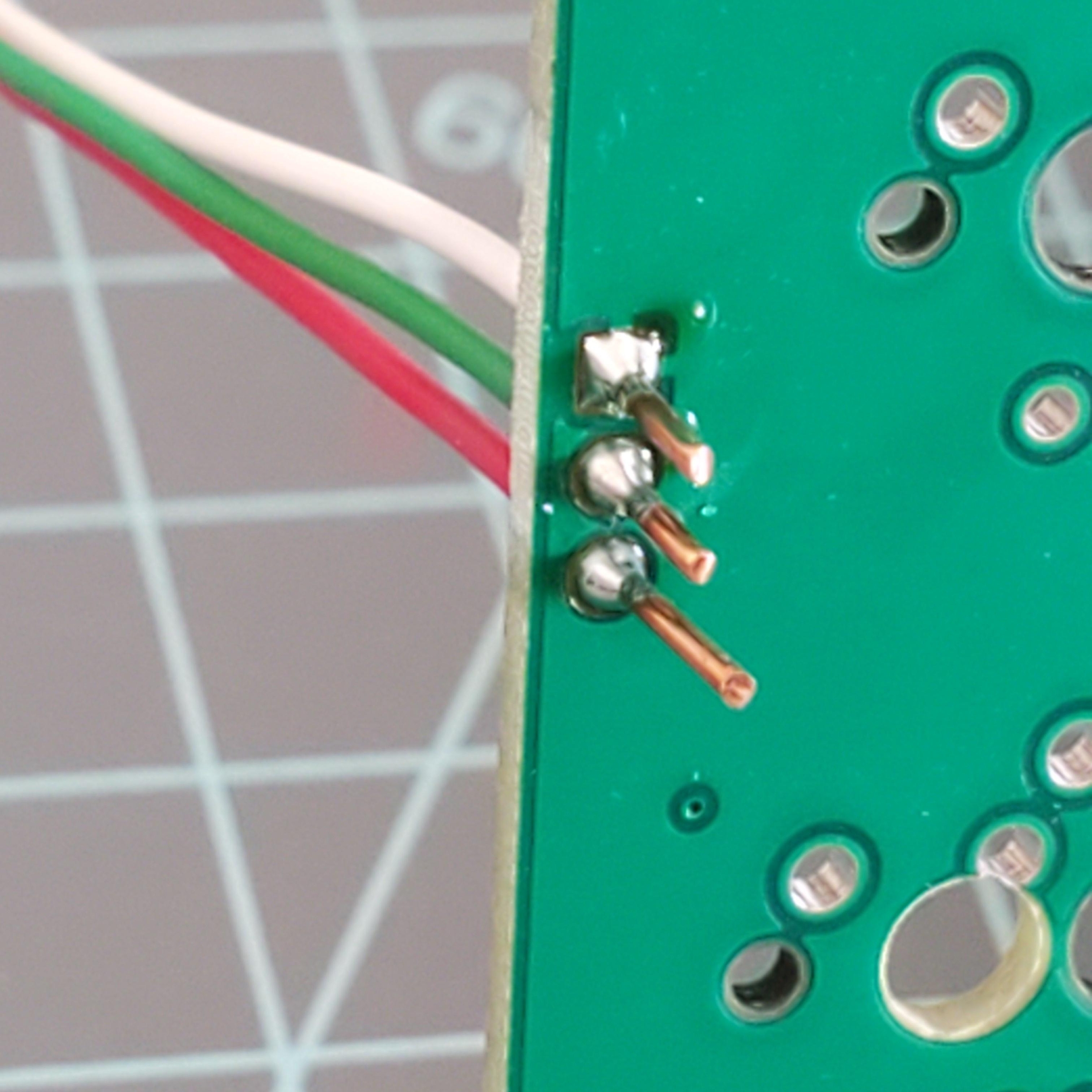
Solder the wires in place, then trim the excess copper.
Repeat Step 5 for the opposite side, unless you just want side glow on one side ¯\_(ツ)_/¯
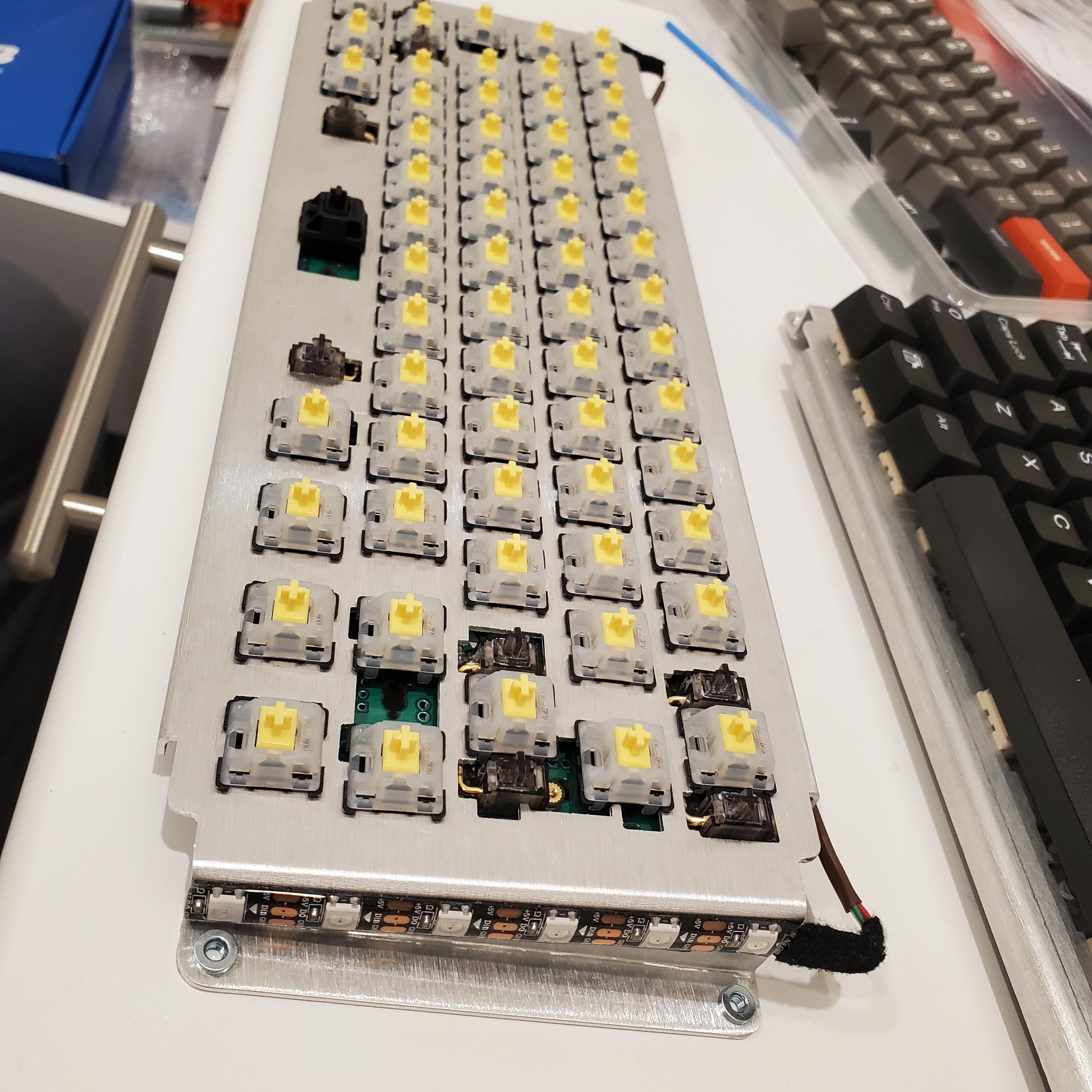
Stick it on the side however you like!
STEP 5: Assemble PCB to Plate
Gather the appropriate number of MX style switches of your choosing (sold separately; ~65 switches required)
Mate the Switch Plate together with the PCB [Parts No. 3 & 4]
Be careful with the RGB Side glow wires, if installed: Firmly bend the wires around toward the taller edge of the plate and make a U-turn to keep them in place, with the LEDs facing outward away from the plate.
Now, Push several switches into the plate around the edges and in the middle, and into PCB.
Make sure the switches are all facing the correct orientation and the pins are straight!
Solder these "anchor switches" into place, making sure the switches are all the way into the plate, and the PCB is sitting flat against the switches.
Continue soldering the remainder of the switches in place until your selected layout is achieved. Reminder: the plate controls the possible layouts, not the PCB.
Test fit keycaps to ensure the layout is correct, before soldering, especially on the bottom two rows!
You should test the PCB again at this point. Test all the switches, and the sideglow, if installed.
We recommend you wash your hands after soldering.🧼
STEP 6. Serial Plate on the Bottom Case
Line up the Bottom Gasket with the Bottom Case so that the holes for the badge line up, as well as the semi-circle slots along the front edge.
The bolted joint should be as follows from outside-in:
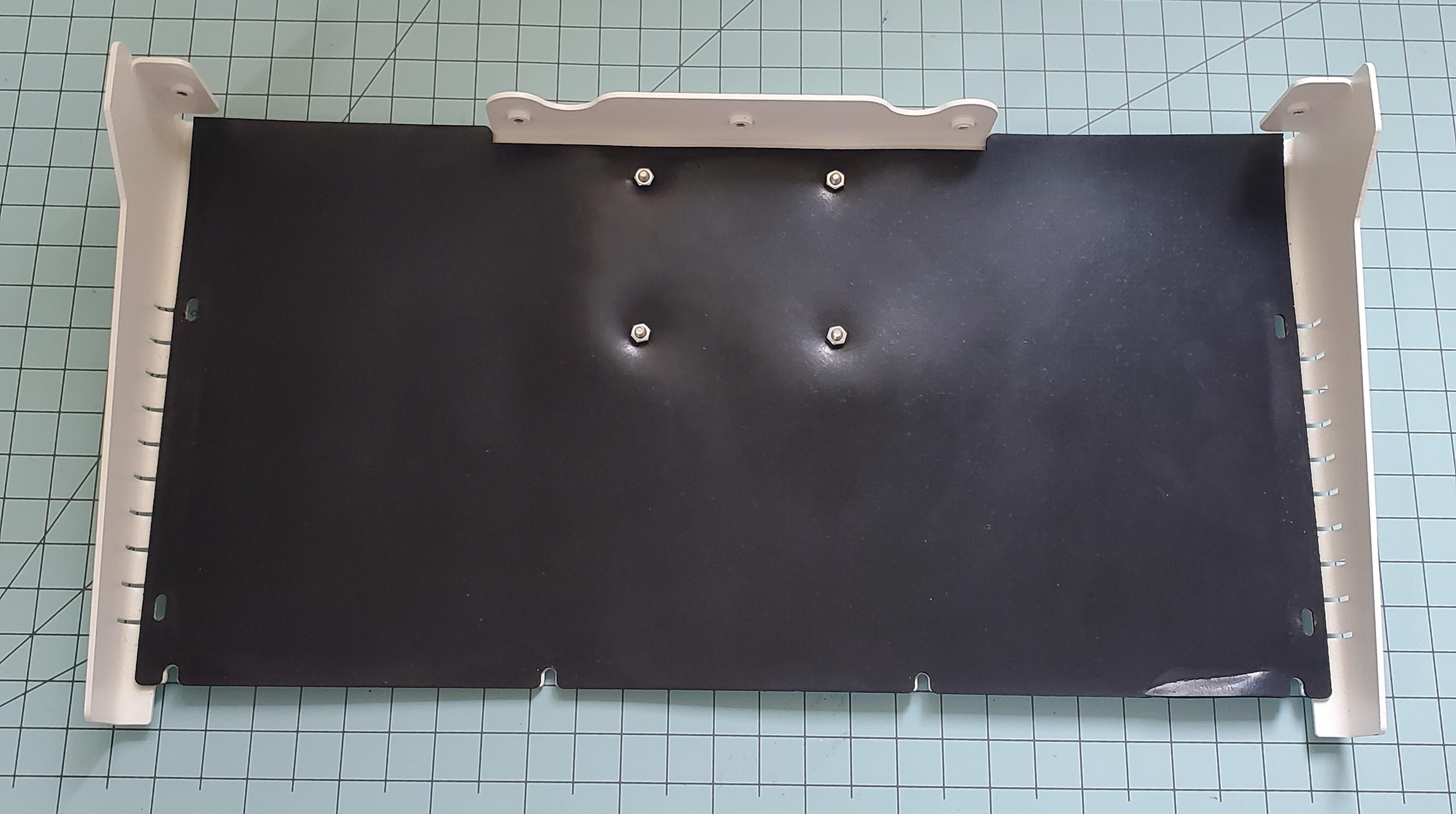
M3 Screw -> Badge -> [Bottom Case] -> Bottom Gasket -> M3 Nut Screw heads should always be on the outside of the case.
Do not over-tighten the screws, you could rip through the rubber. Nobody likes a broken rubber. 🦀
STEP 7: Handle and Cable
Sort of self-explanatory. Make sure the handle's washers and nuts are on the inside of the case.
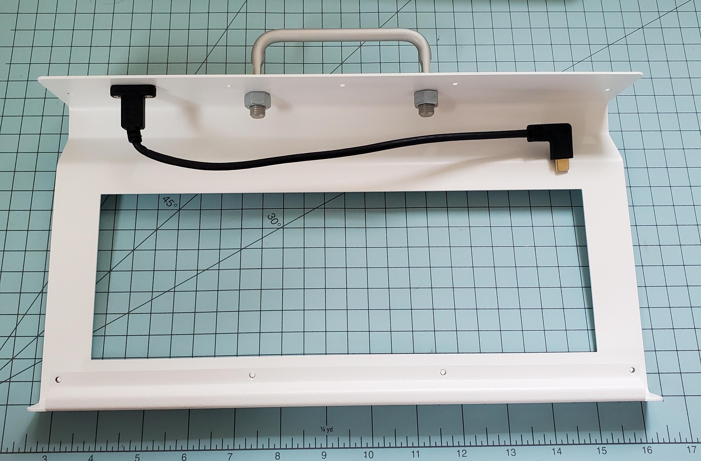
Do NOT Overtighten the nuts on the handle. The handle will not articulate properly, due too excessive friction from turning the mounting studs.
Install the cable to the Top Case using two M3 screws. Apply an even amount of installation torque on both screws. When installed, the cable should be bent toward the inside of the case.
For some comic relief/example of how not to do it: watch this clip twice. The second time at 0.25x speed. Reminder, the Saturn-60 has a lot of gravity. 🦖
The silver aluminum (default) handles benefit greatly from some lubrication on their hinge mechanism. Grab your Top Case half and flip if over Take the frame-shaped Top Gasket foam [Part No. 8] and place it around the cutout of the Top Case:
STEP 8: Foam and Plate Assembly
Add the Upper Gasket foam around the cutout of the Top Case:
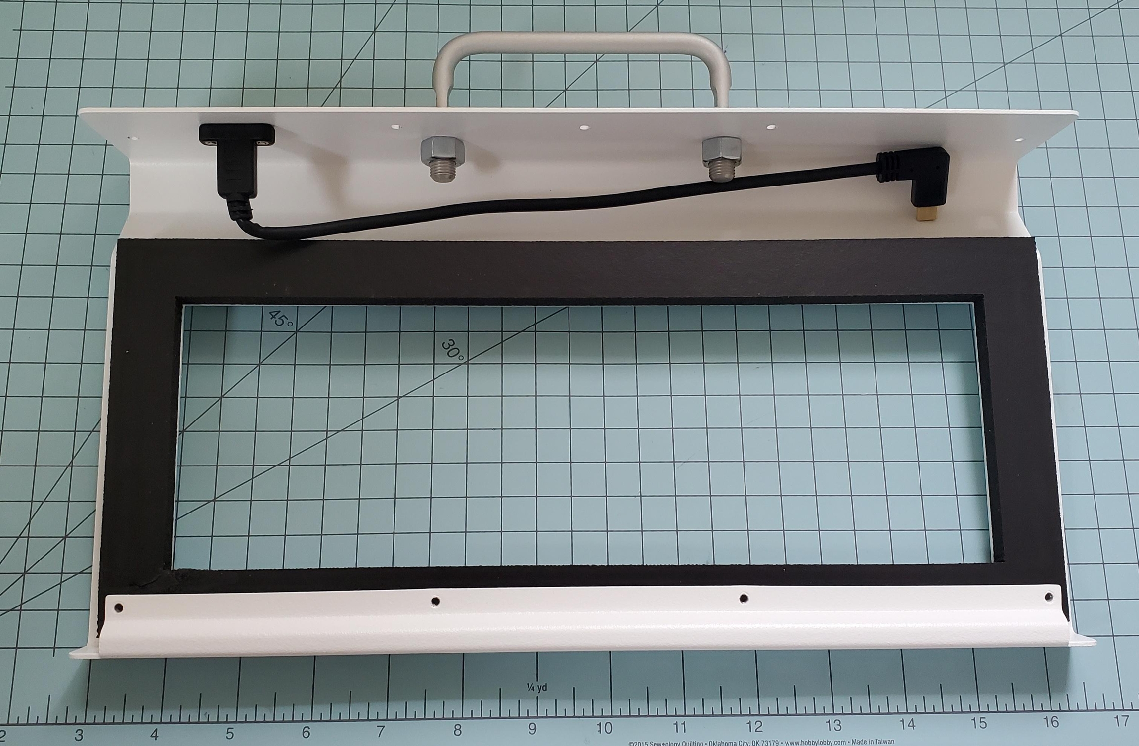
The Upper Gasket is optional, but it helps reduce echoes and keeps debris out of the keyboard.
If you have some thin double-sided tape, it will help keep the foam in place on the Top Case while you do the next steps.
Place the Plate+PCB assembly into the foam like so, and plug in the USB cable:
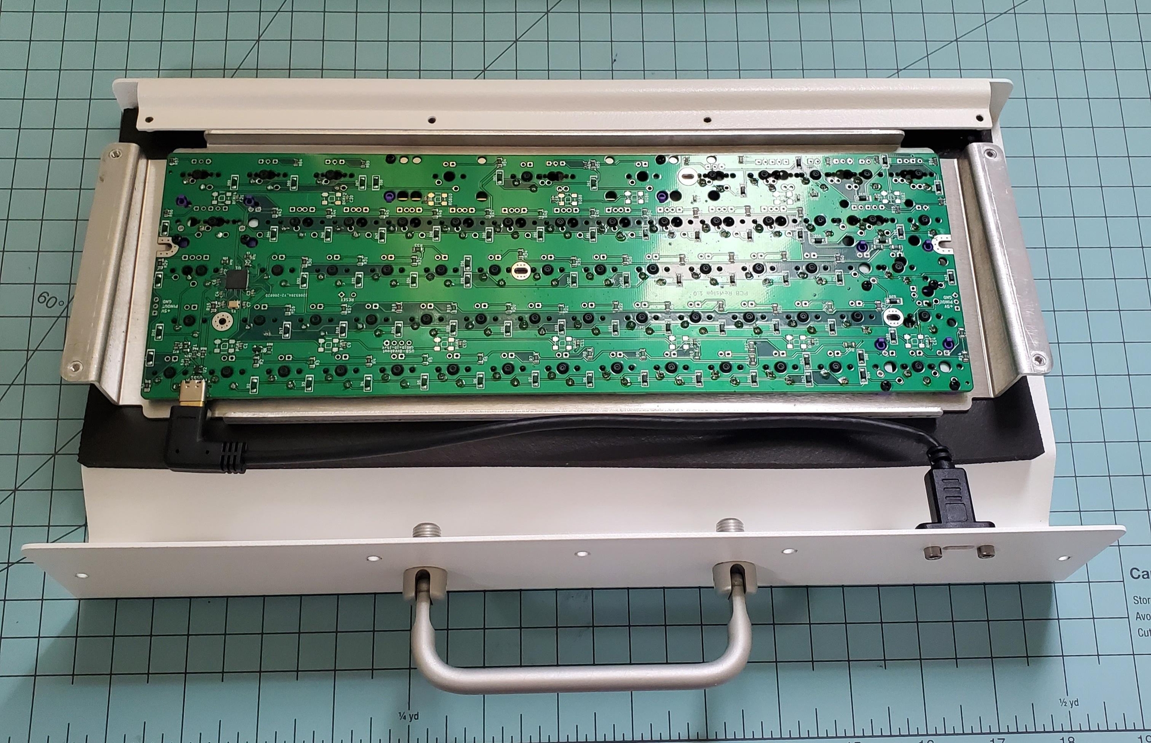
Then, tuck the front edge of the plate underneath the PEM® nuts inside the front lip of the case:
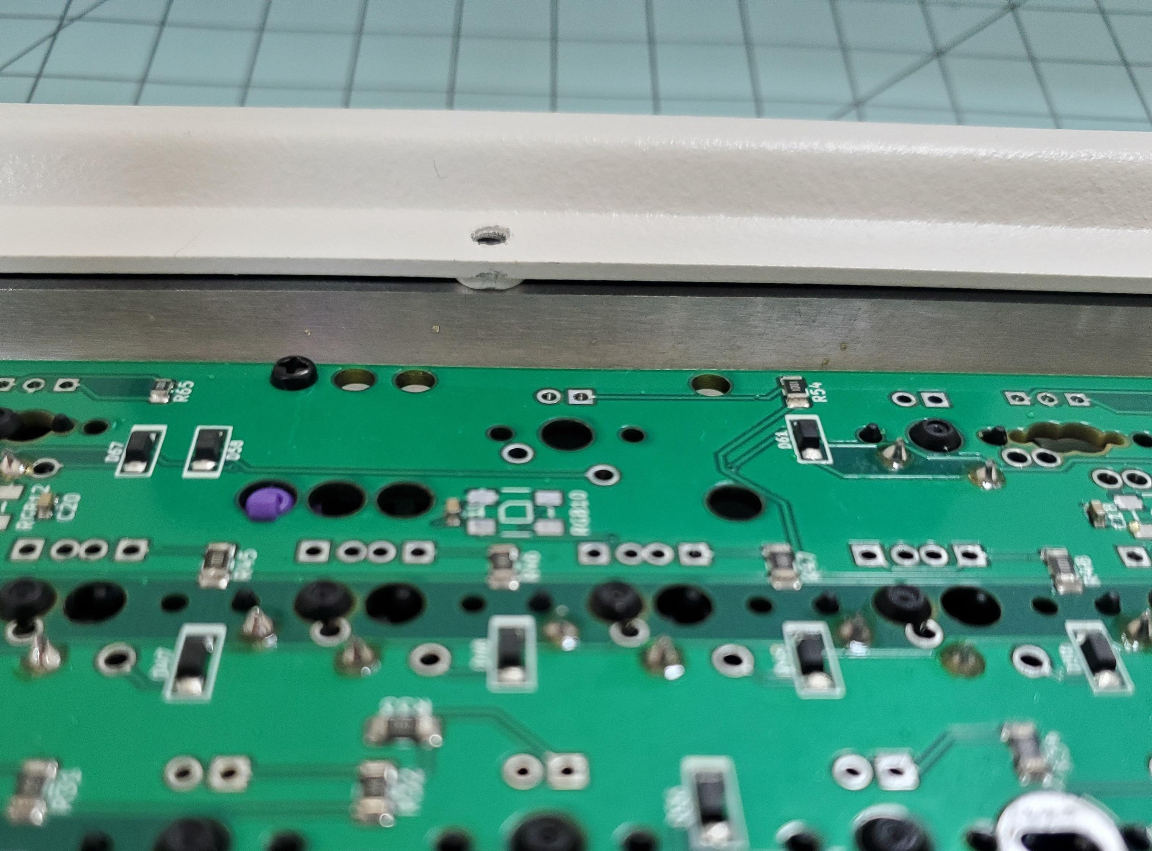
If you wish, you can now add the inside part of the Upper Gasket:
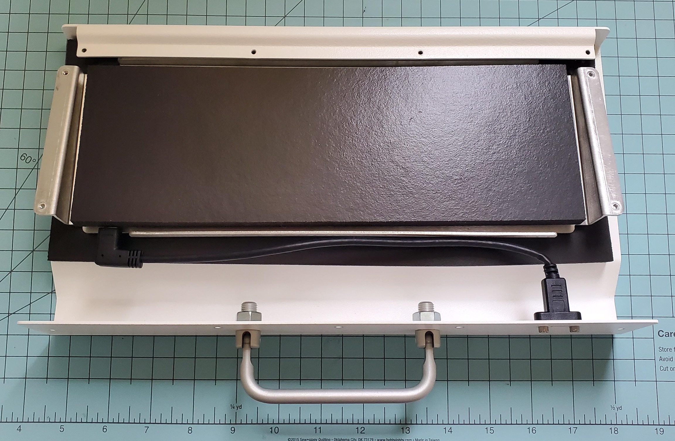
Now, make sure the plate is even side-to-side, and the foam is as far back as the USB connector allows:
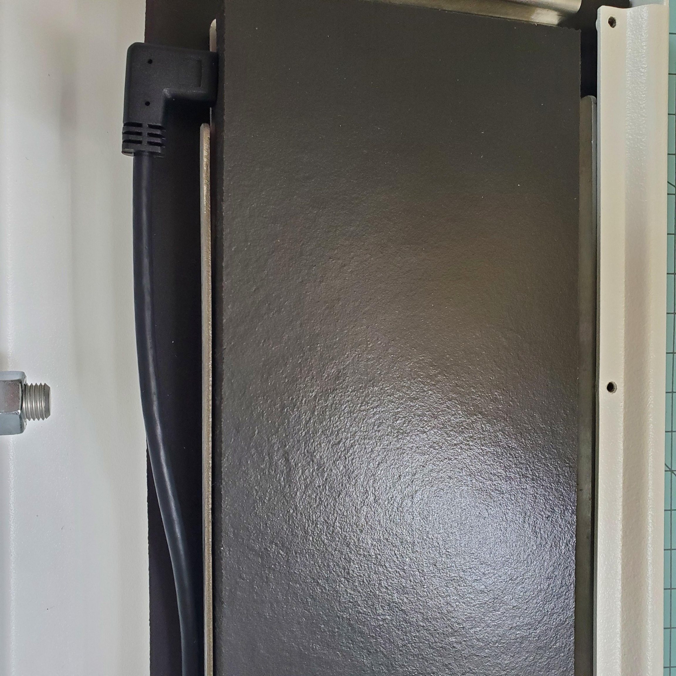
Take a break because this next step requires finesse. ⛳ You've probably been breathing solder fumes, so go outside for a bit, drink some water, and then come back.
STEP 9: Fitting the Two Case Halves
You may want to put something (like a folded-up towel) underneath the front edge of the Top Case to allow some space between the opening and the work surface.
Invert the Bottom Case Assembly from Step 6.
Lower the assembly onto the Top Case (which is upside-down on the table), and check that the cable is not interfering before applying force to close.
Install the screws on the bottom of the case. All on the bottom, with the exception of the Serial Plate should have washers.
Keep the screws that hold the plate a bit loose for now. You may need to re-adjust the plate left or right to get the holes to line up.
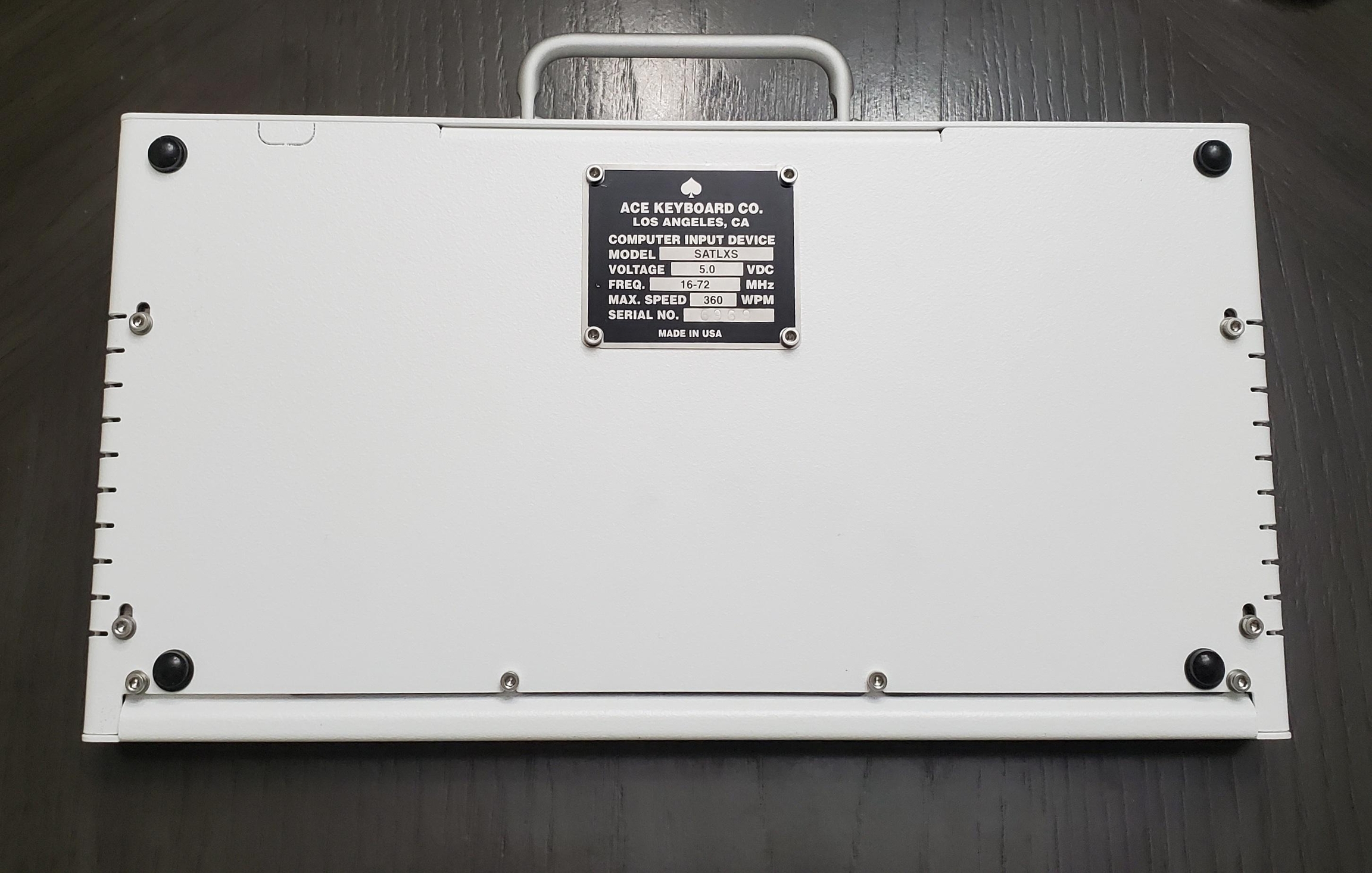
Now, screw in the screws on the back wall of the keyboard.
You can now flip the whole thing over and test the fit of the foam and plate assembly.
If the foam is too close to the switches: gently nudge it back with the hex key (but not too far!!!):
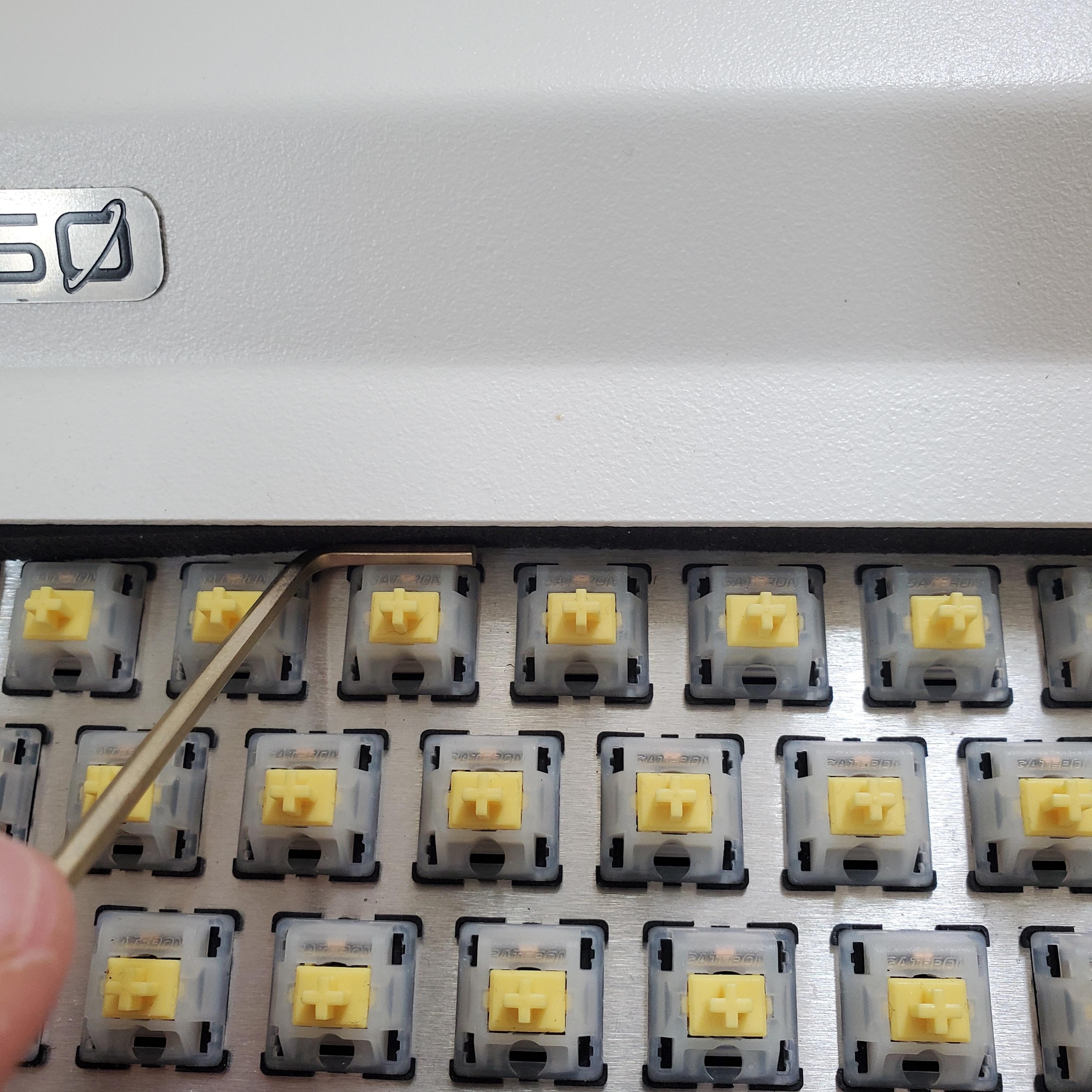
Then, line up the Plate+PCB Assembly:
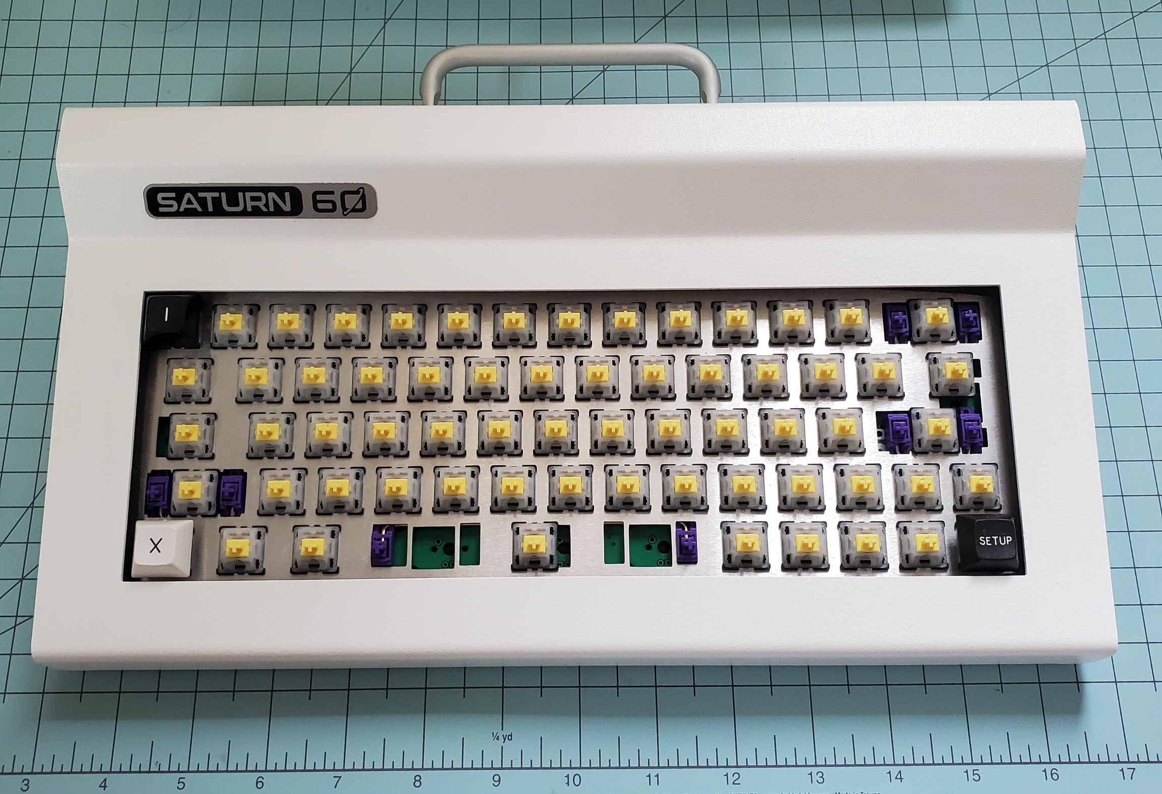
For proper alignment, you may need to shift the plate toward the front of the case. There might be a lot of friction so take your time. Installing one keycap in each corner will help you determine when the plate is in the right location. When it is, you should tighten down all four screws that hold the plate.
You may need to tighten the screws on the bottom that hold the plate at the same time as you are shifting the plate toward the front

The image above shows the final-assembly positions of the plate screws. When they are in this position, the keycaps should not hit the case. 🥳 After this step, you can install the rest of the keycaps and clack away! ⚡
STEP 10: Saturn-60 Badge (Optional)
Clean the area where the badge will go using soapy water or rubbing alcohol (not denatured alcohol). Make sure the surface is dry.
Use 0.94" (24mm) masking tape to align the badge rectilinearly with the case. We know you can do it by eye, but trust us. Just get the tape.👾
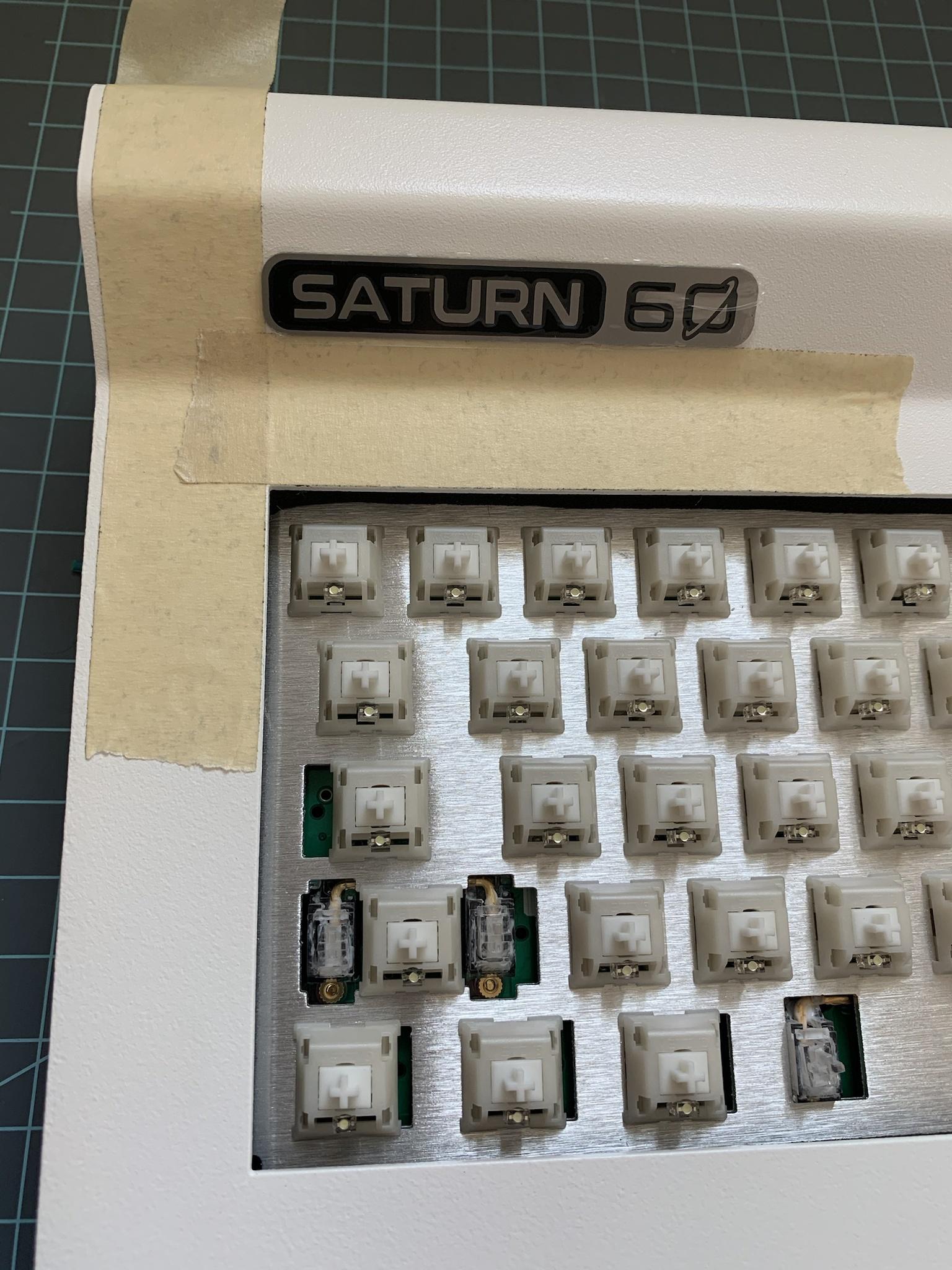
The adhesive is permanent. Once the badge has been placed, it probably will not come off without a fight. 🥊
STEP 11: Rubber Feet (Optional)
If you plan to use the keyboard on hard surfaces, the four included rubber bumpers should be used (Part #15). These bumpers are non-marking.
Identify a place to put these four on the Bottom Case half, as far to the corners as possible. Clean the powdercoated surface; view the previous step for info on cleaning the surface.
Peel off the feet one-by-one and press them onto the case firmly.🐾
For the best adhesive hold it is highly recommended to let the adhesive settle in place for 24 hours. Leave the keyboard on your desk overnight or somewhere flat where it will not shift for as long as possible.
STEP 12: Programming
The Titan60 is QMK and VIA compatible.
Here are the keymaps:


Feedback
If you have any feedback about this build guide, or would like to share your tips and tricks with us, please shoot us an email or join the Discord! We would love to hear from you.
Last updated